Overview
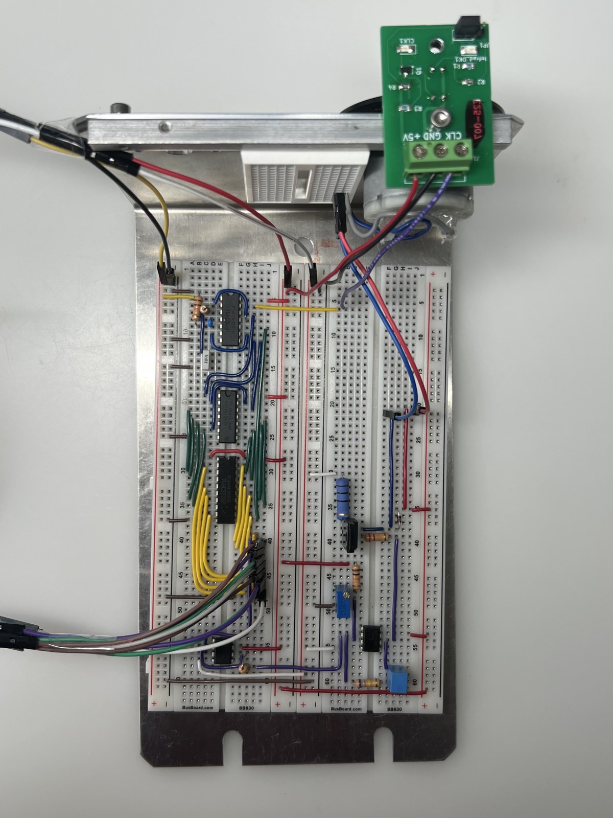
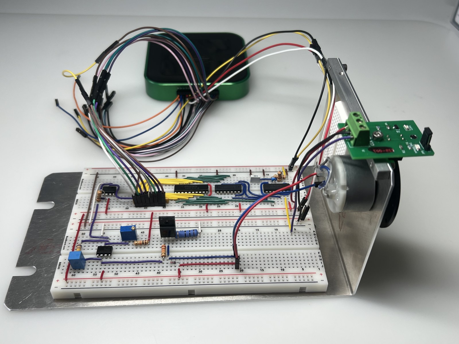
The goal of this project was to build a circuit that actively controls the speed of a DC motor. A slotted disc on the motor passes in front of an optical sensor, and the circuit counts the resulting pulses over a fixed time window to measure how fast the motor is spinning. That count is converted into a voltage and compared with a setpoint, and the difference adjusts the current through the motor until its speed matches. I built and tested each stage on its own before connecting them into the complete feedback loop.
How It Works
Timing Signals
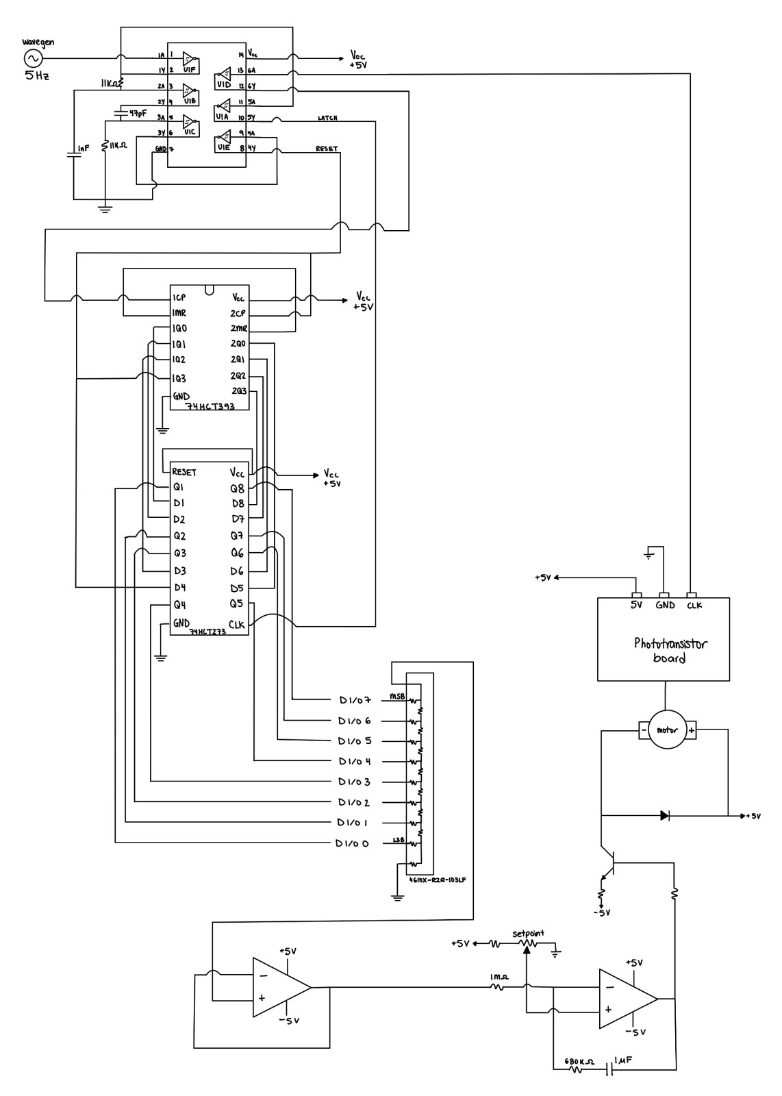
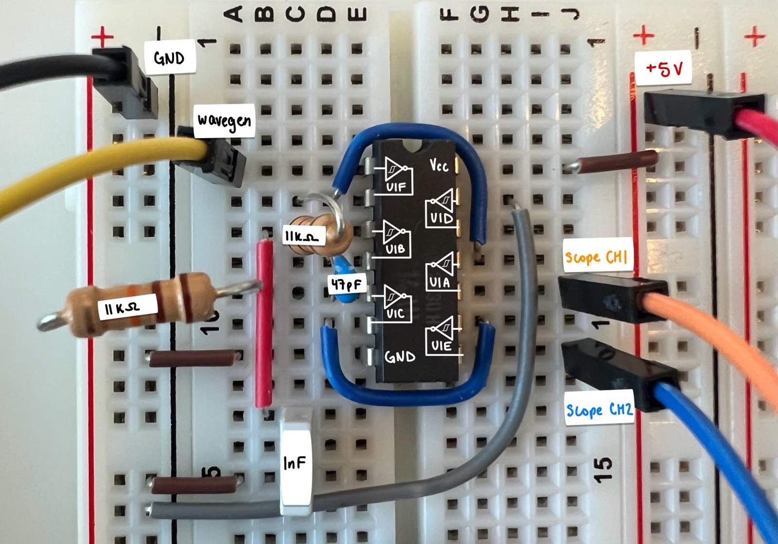
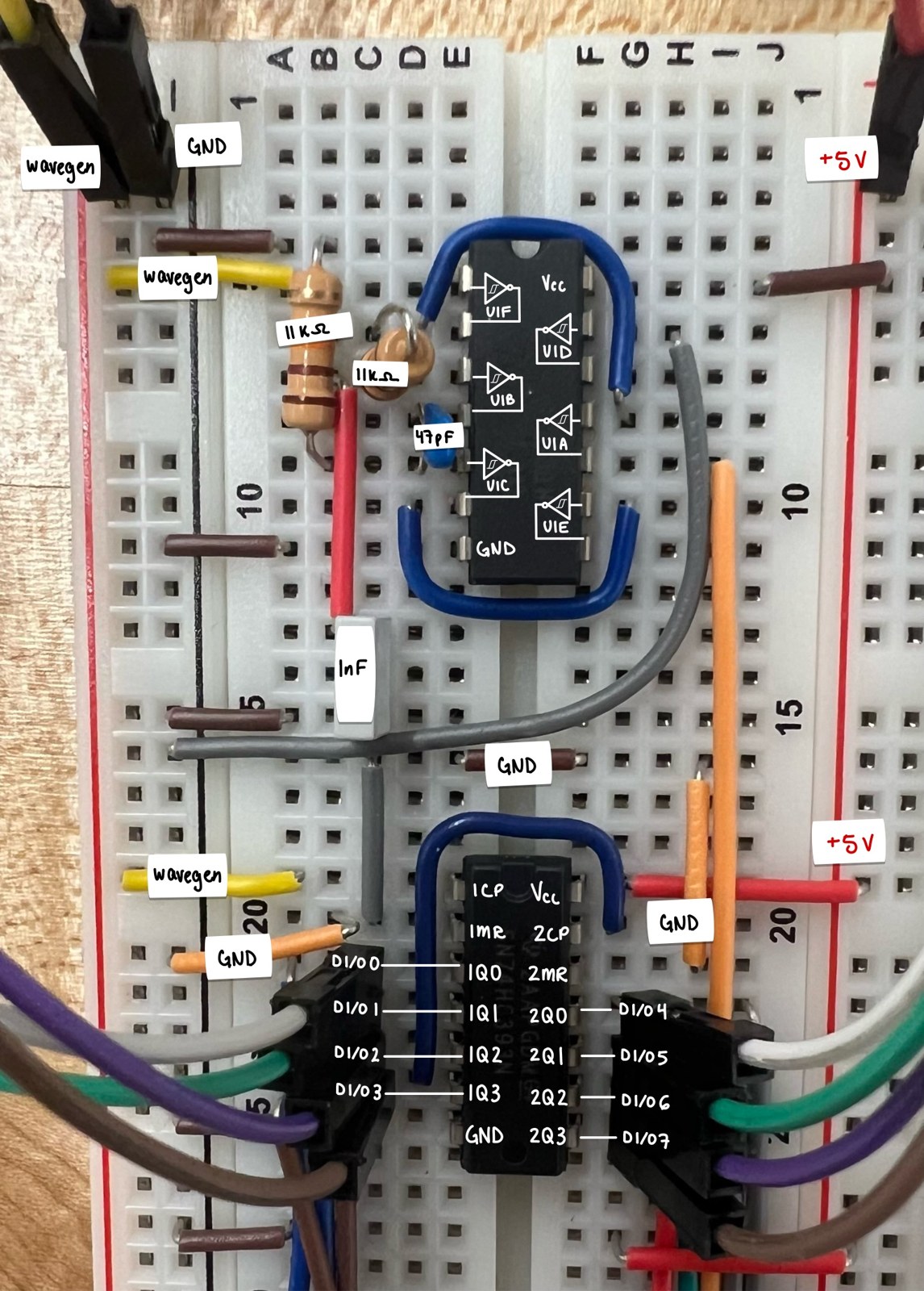
A Schmitt-trigger inverter generates the two timing signals that run the system: a 5 Hz LATCH signal that marks the end of each measurement window, and a short RESET pulse just after it that clears the counter for the next window. Two RC networks set the delay between them and the width of the RESET pulse. I verified both on the oscilloscope against their calculated time constants.

Speed Sensing and Counting
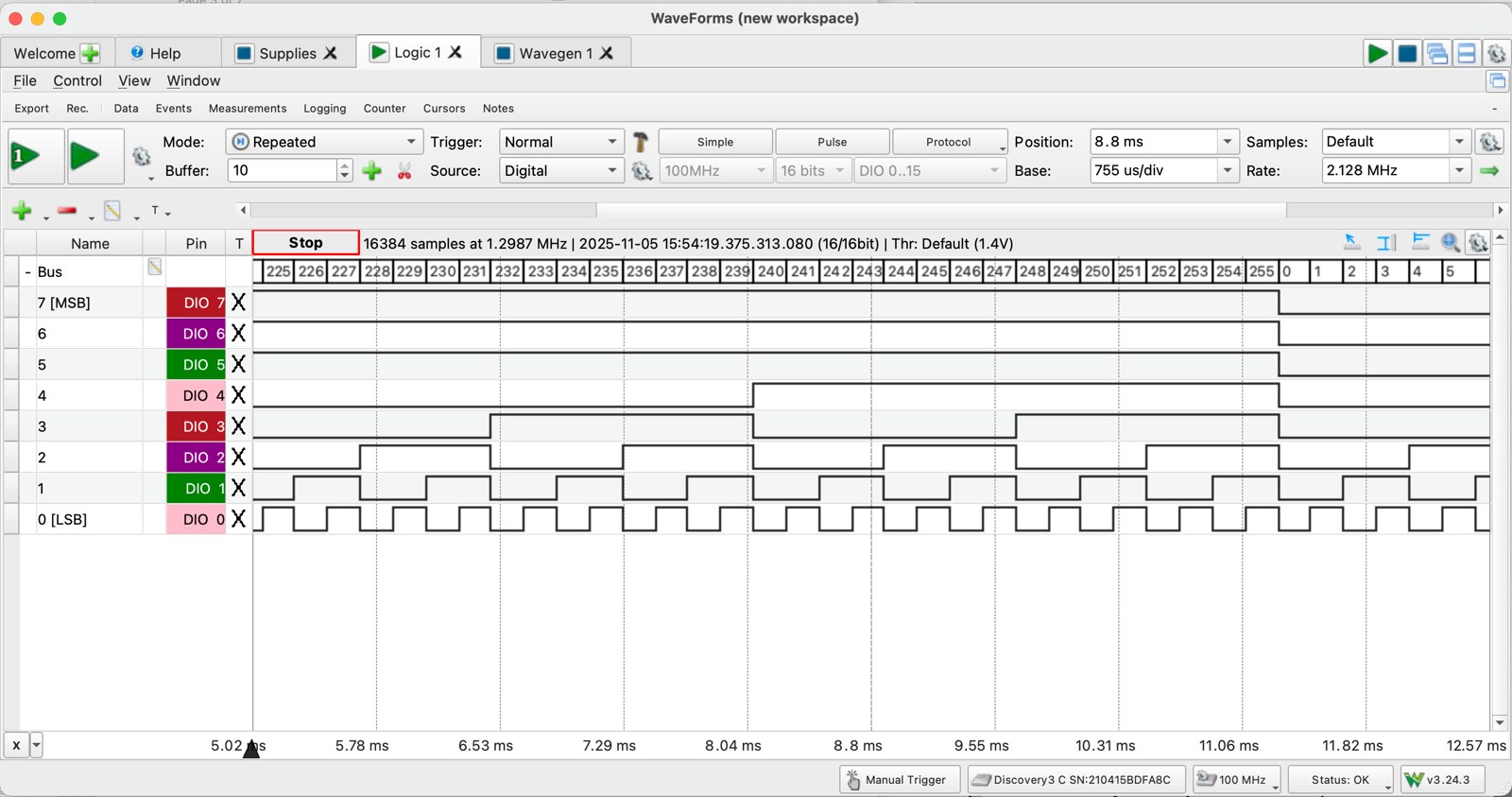
Each time a hole in the motor’s disc passes the phototransistor, it produces a pulse, which the inverter cleans into a sharp digital edge. Two 4-bit counter chips chained into an 8-bit counter tally these pulses during each window.
Latch and DAC
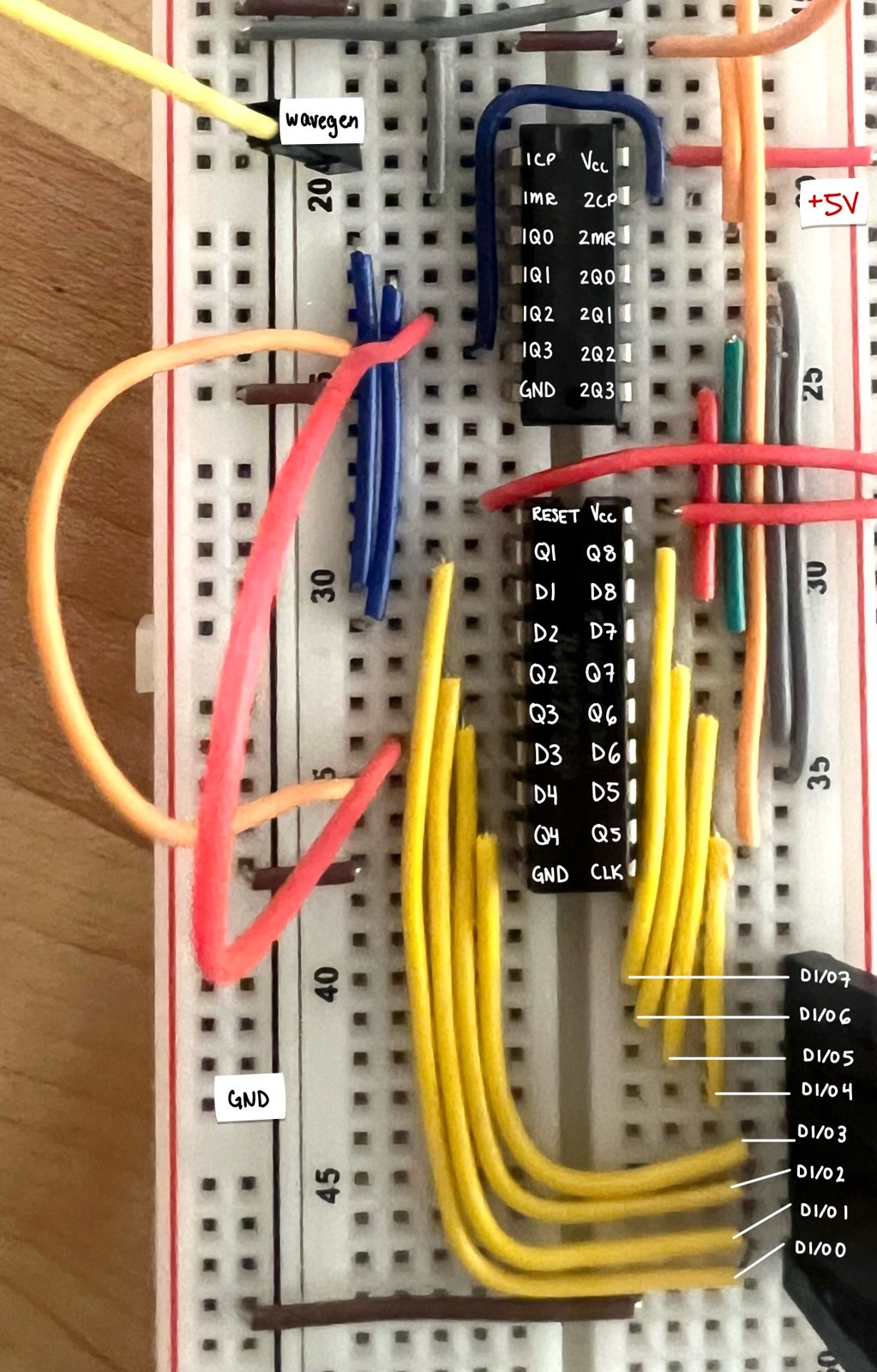
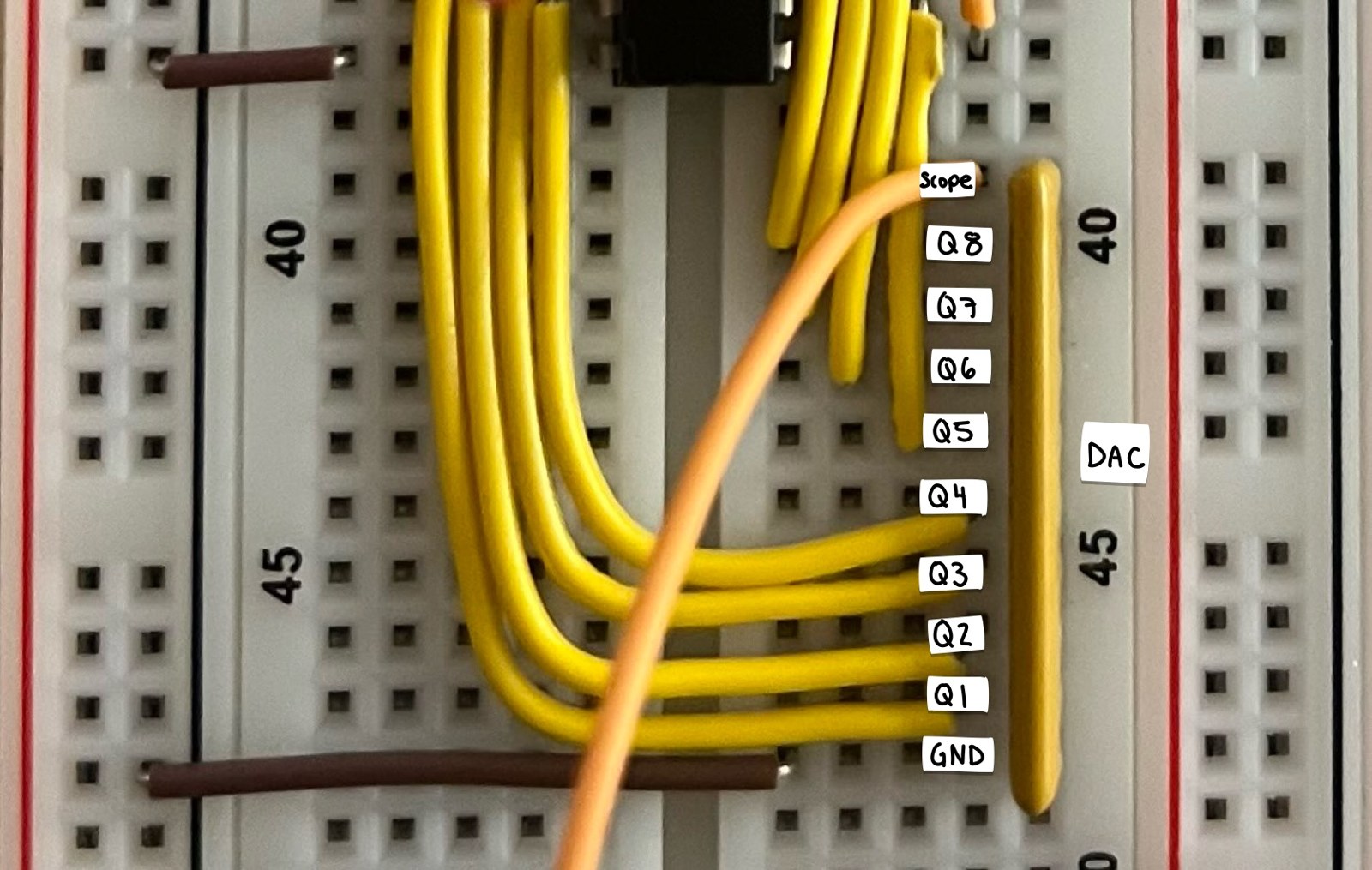
The counter keeps running, so a D-latch captures its value at each LATCH edge and holds it steady. An 8-bit R–2R resistor ladder DAC then converts the held count into a proportional voltage, which represents the motor’s measured speed.
Error Amplifier and Motor Driver
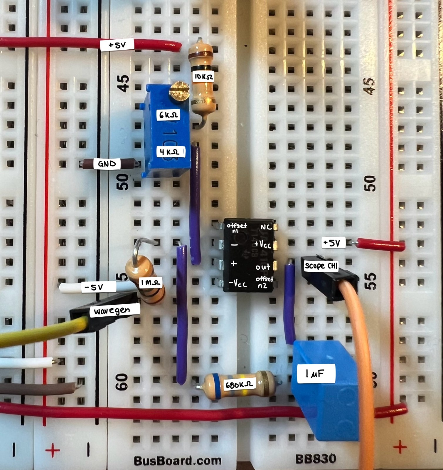
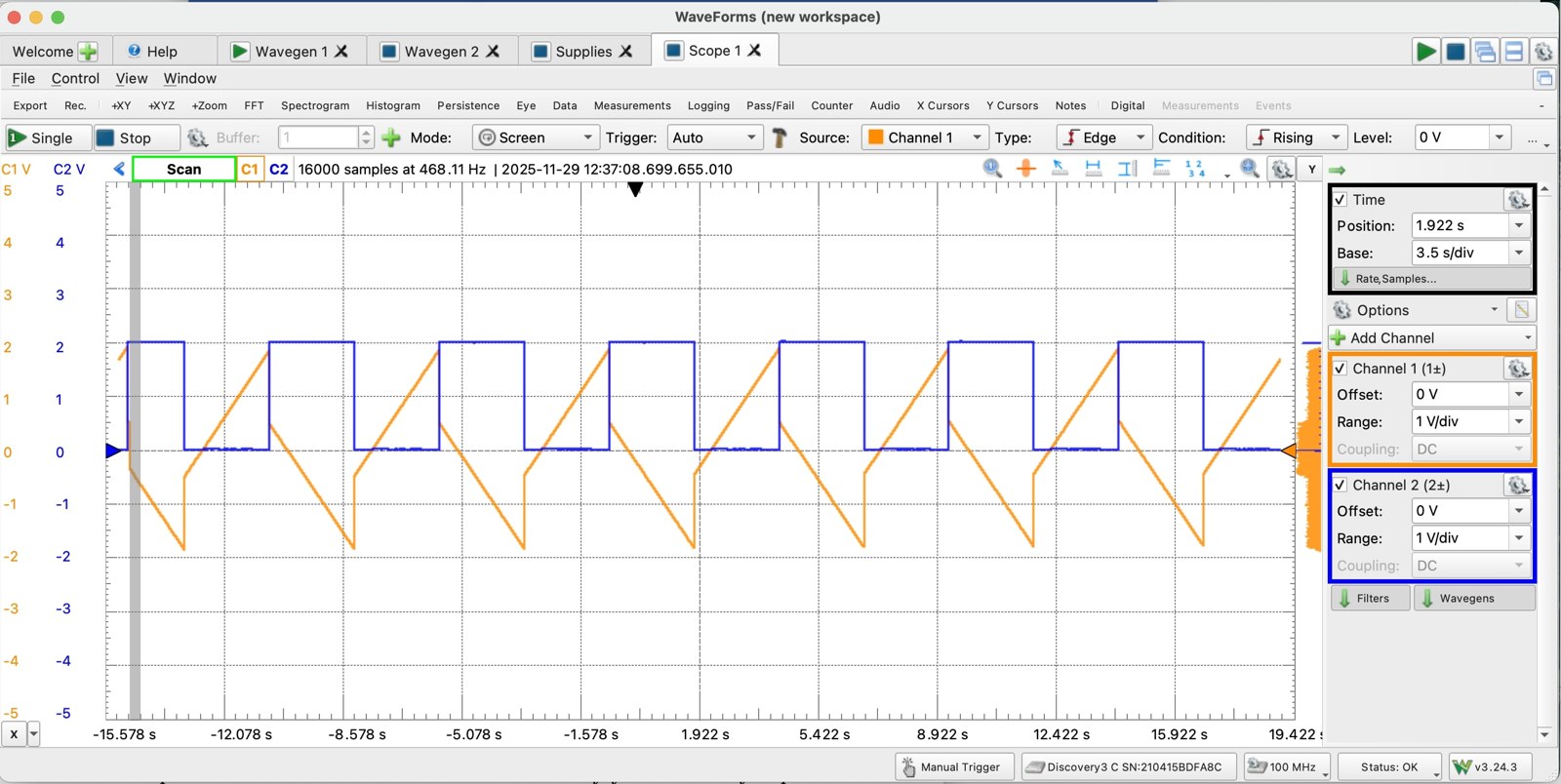
An op-amp integrating amplifier compares the measured speed voltage with a setpoint from a potentiometer. If the motor is too slow, its output ramps up; if it is too fast, its output ramps down. That output drives a BJT, which controls how much current flows through the motor.
Testing and Debugging
I tested each stage on its own before closing the loop, which made problems easier to trace to their source. A few examples:
- Counter reset: The latched values were climbing in steps of 10 instead of holding steady. I traced this to the counter’s reset pins not being connected to the RESET pulse.
- Motor not spinning: After confirming each stage of the circuit was working, I found the motor’s disc was rubbing against its housing, which was a mechanical fix rather than an electrical one.
- Faulty sensor board: Scoping the sensor’s output showed its pulses weren’t dropping low enough to register. Swapping in a different board confirmed the original was defective.
Results
With the loop closed, turning the potentiometer smoothly changed the motor’s speed, and the measured count held steady at each setpoint, showing the circuit was holding the speed constant. I achieved controlled speeds from about 300 to 2,610 RPM. At the top of that range, the count stopped increasing while the amplifier’s output kept climbing. That showed the control loop was still trying to speed the motor up and that the motor itself, not the circuit, was the limiting factor.