Competition Overview
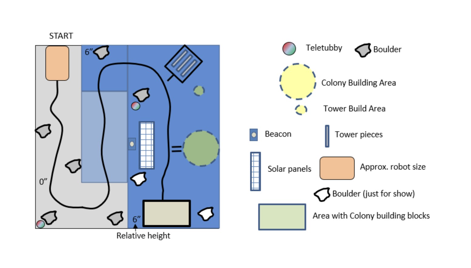
ENPH 253 is UBC Engineering Physics’ summer design course, in which teams of four design, build, and program a fully autonomous robot from scratch and then compete head-to-head. The 2026 competition took place on an 8 ft × 8 ft course with a ramp and an elevated section, where robots followed a taped path and earned points by completing a variety of sensing and collection tasks. These included identifying and collecting a mineral rock hidden among decoy boulders, removing the protective cover from a solar panel located only by an infrared beacon, and spotting Teletubby dolls hidden behind the boulders.
Project Description
Robot Design
As the lead mechanical engineer, I was responsible for most of the robot’s mechanical design, from concept through manufacturing and testing. I worked from the rulebook to define the reaches, heights, grip widths, and clearances each task required, authored the mechanical section of our design proposal, modelled the robot in Onshape, and manufactured and assembled each iteration. My teammates focused primarily on the electronics and software, with one also designing the robot’s final gripper, and much of my role was defining the mechanical interfaces their systems depended on.
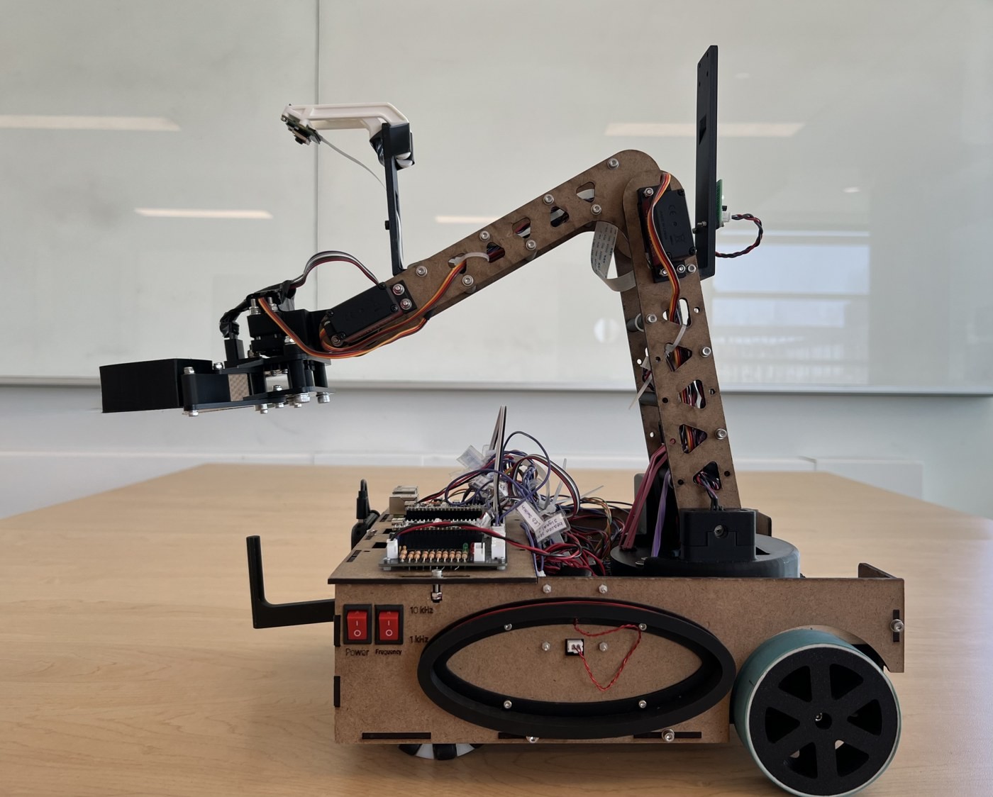
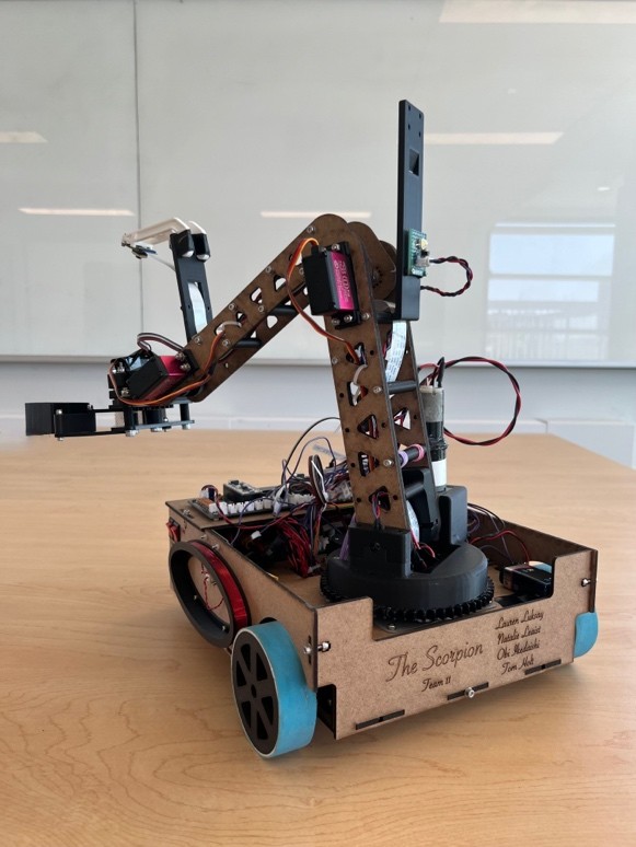
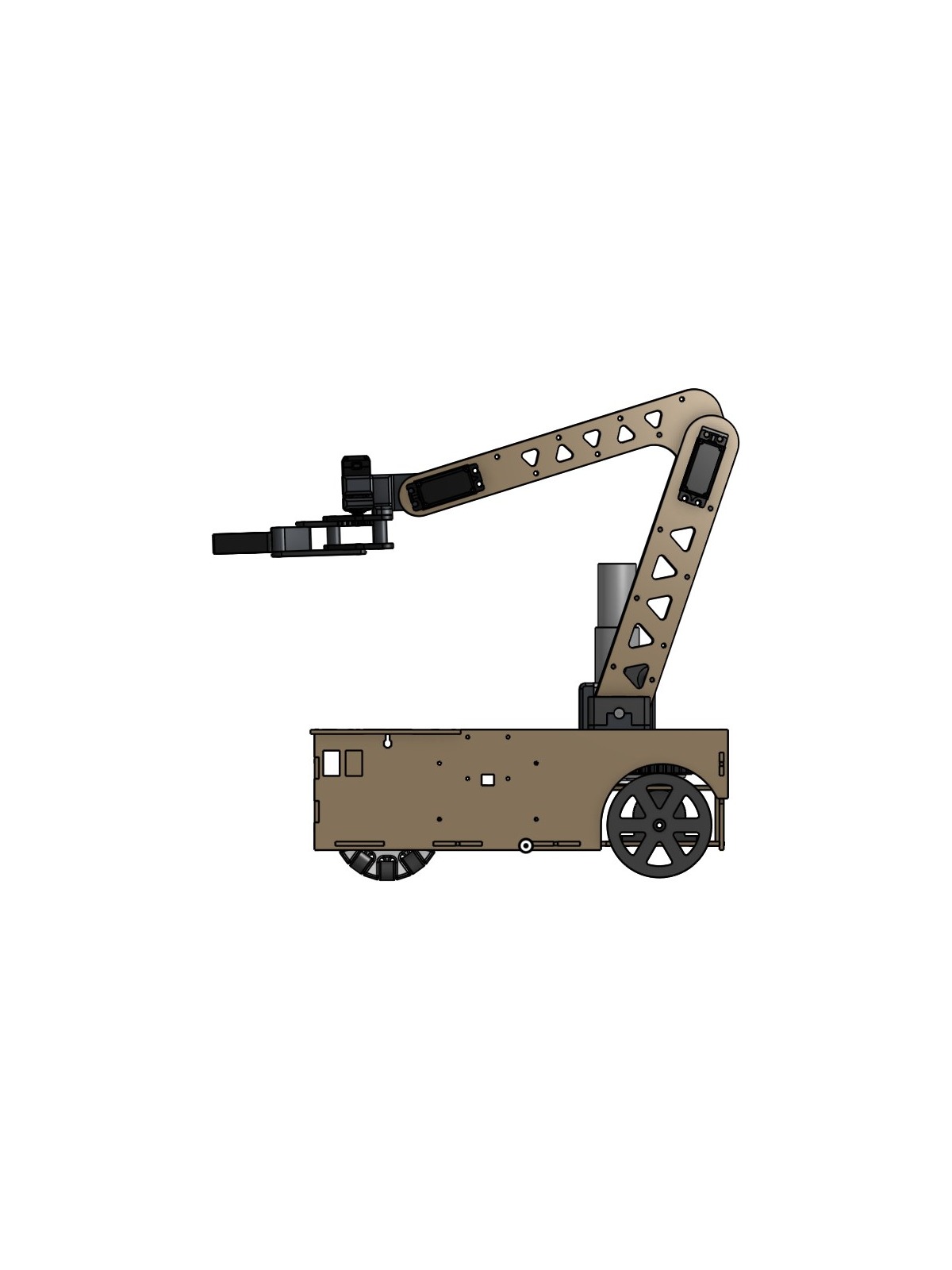
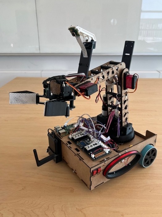
The final robot is a compact differential-drive platform carrying a four-degree-of-freedom arm (a rotating turret, shoulder, elbow, and wrist) with a gripper and a time-of-flight LiDAR sensor mounted in the claw.
Chassis and Drivetrain
The robot uses rear-wheel differential drive, with each rear wheel driven by its own geared DC motor and two passive omni wheels at the front. I chose this layout because it is the simplest platform to line-follow with and control precisely, it allows the robot to pivot in place to aim at task targets, and it keeps the weight over the driven wheels for traction on the ramp. I selected geared motors with integrated encoders, which let the software stop the robot at repeatable distances along the course and correct for mismatched motor speeds.
The chassis went through several redesigns, and the most important was driven by the robot’s centre of mass. The arm was originally mounted near the front of the chassis, which placed the centre of mass well forward of the drive axle and gave the robot a large moment of inertia about its turning axis. Every small steering correction caused the robot to oscillate, which made line following difficult to tune. I redesigned the chassis to mount the arm lower and directly over the rear drive wheels; moving the mass closer to the axis of rotation reduced the oscillation and made the robot much easier to control. I tested each version with ramp climbs, in-place pivots, and stopping-distance measurements to confirm traction and repeatability.
Frame
The frame is the box structure built up from the chassis, which houses the control boards, battery, and wiring and carries the components the other subsystems relied on. I designed mounts for the metal-detector coils on the sides of the robot at rock height, the infrared line sensors beneath the front, a camera with a clear view past the arm for Teletubby detection, and the onboard basket that collects the rock. I also routed the arm’s wiring through the rotating turret with enough slack for its full range of motion.
Arm
The arm is a four-degree-of-freedom serial arm: a turret that rotates the whole arm, followed by shoulder, elbow, and wrist joints that work in a vertical plane. This was the simplest arrangement that could place the claw anywhere in front of or beside the robot at a controlled angle, which every task needed: approaching a rock with the claw level, reaching the loop on the solar panel cover, and pointing the LiDAR straight down to scan.
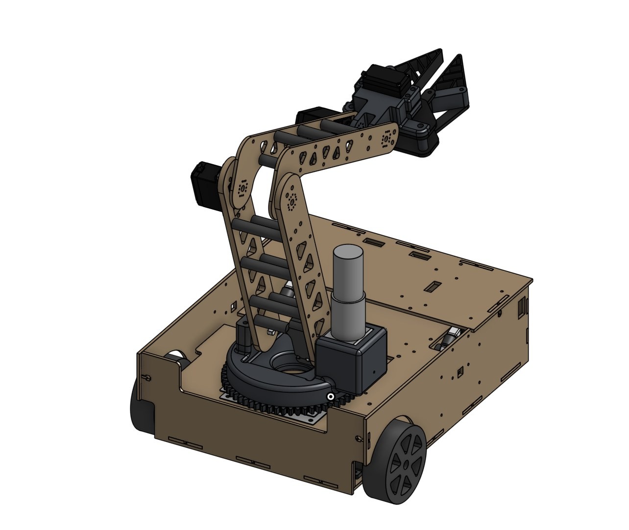
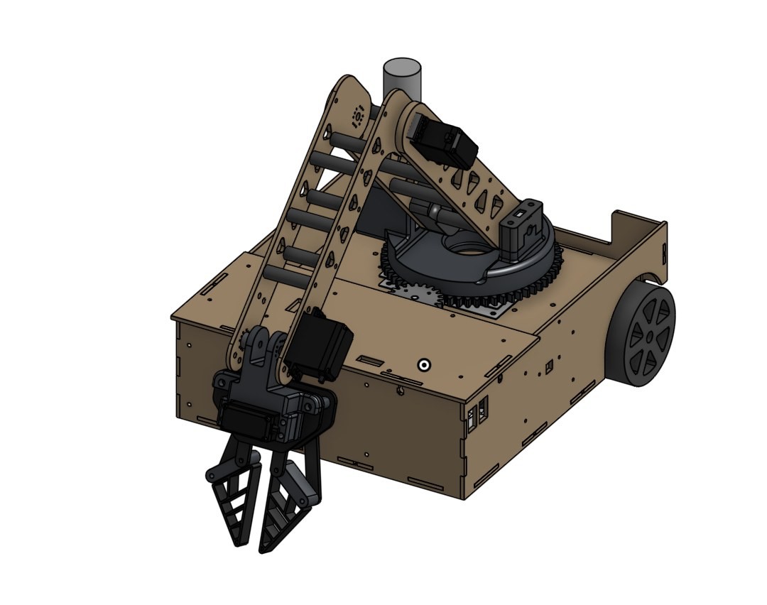
Turret. A stepper motor drives the turret through a 3:1 spur-gear reduction into a ring gear on the rotating platform. I changed from the servo in our original proposal to a stepper because the tasks needed fine, repeatable positioning over a wide range of rotation, and the gear reduction also multiplied the motor’s holding torque against the extended arm. Early versions had enough backlash and platform tilt to move the claw several millimetres at full reach, which I reduced in later versions by stiffening the platform and improving the bearing support and gear mesh.
Joint actuators. I calculated the torque required at each joint at full extension early in the design. Those numbers made it clear that the shoulder needed a geared DC motor rather than a servo, so I specified one and added a potentiometer for closed-loop position feedback. The elbow and wrist were within the range of high-torque servos on paper, but once the real links, servos, sensor, and a payload were on the arm, testing showed both were underpowered, and I upgraded them to higher-torque units.
Links. The first version of the arm used acrylic side plates that were heavier and wider than they needed to be, and because that mass sat at the end of a long arm, it increased the load on the shoulder. I redesigned the links as narrower laser-cut MDF side plates joined by 3D-printed standoffs, forming a light box section that stays stiff in bending and torsion while weighing significantly less. I also analysed the arm’s workspace against the chassis and joint limits, which showed that moving the joints one at a time could swing the arm into the chassis, so the software teammates coordinated all joints when moving between poses.
Gripper. I designed, built, and tested a gear-driven interlacing claw that gripped objects securely and ran smoothly. A teammate then proposed a compliant gripper that achieved the same grip with fewer moving parts, less mass at the end of the arm, and no gear train to wear or align. The team adopted his design, and I integrated it, designing its interface to the wrist and the mount that holds the LiDAR inside the claw body. His design was simpler and lighter, and adopting it was the right choice for the robot.
Electronics and Software
Beyond the mechanical design, I contributed to two parts of the robot’s electronics and software.
LiDAR-Guided Pickup
Two of our tasks required the arm to grasp a target whose exact position was not known in advance: the rock, because the robot’s stopping position varied by a few centimetres from run to run, and the fabric loop on the solar panel cover, which could be located only by the beacon above it. The gripper also had little tolerance for being aimed too close, since the claw could knock a rock over before the fingers closed. To locate both targets before grasping, our team used a VL53L1X time-of-flight sensor, and I designed a mount that places it inside the claw, so the sensor moves with the arm and anything it detects is located directly in the arm’s coordinates.
Because the sensor’s beam points along the claw, I used the Onshape model to measure exactly where it sits relative to the grip point and provided those offsets to the software as constants. I then defined the scan strategy used for both tasks: the arm sweeps the beam across the search area by rotating only the turret, its most precise joint, stopping for a fresh reading at each point. For the rock, the claw points straight down and the rock’s position is found from the dip in the readings as the beam passes over it. For the solar panel, the sweep finds the beacon post, which sits directly above the cover loop. In both cases, the arm then corrects for the sensor offset and moves in to grasp the target. My teammates implemented the scan routines in the firmware.
PCB Design
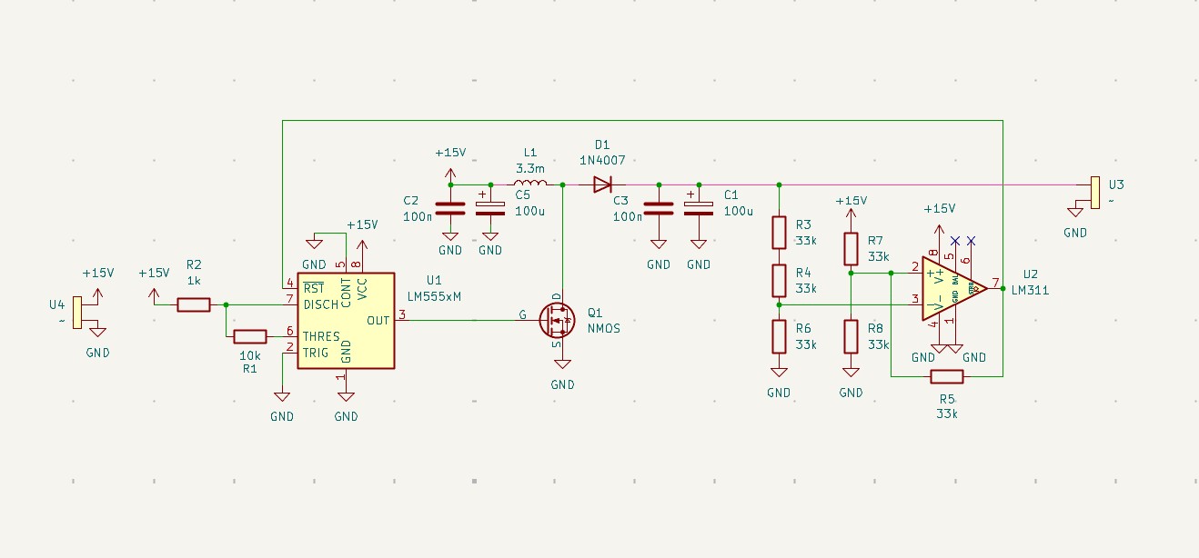
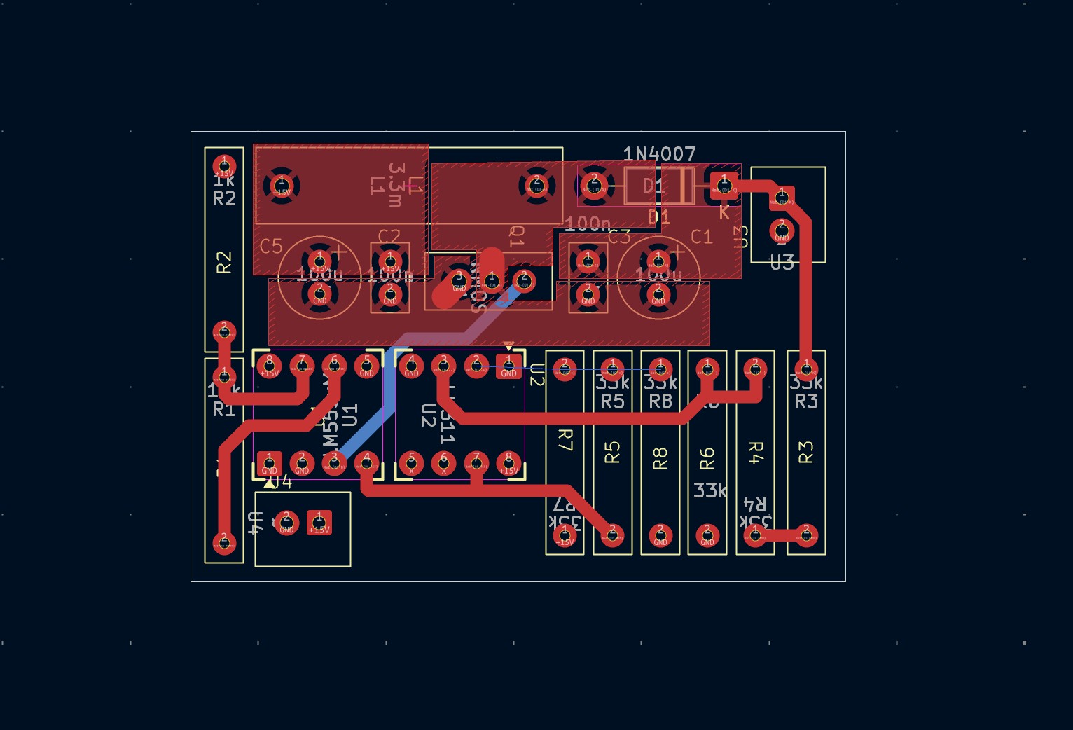
I designed a printed circuit board in KiCad for a boost converter, which was integrated into the robot’s H-bridge motor drivers to provide their higher-voltage supply. A 555 timer switches a MOSFET to step up the supply voltage through an inductor and diode, while an LM311 comparator monitors the output through a voltage divider and turns the switching on and off to regulate it. I created the schematic and laid out the board, routing the traces and placing components to keep the layout compact.
Design and Manufacturing
I modelled the robot in Onshape and manufactured most of its parts myself, choosing each process for how quickly it let me build and test a new version. Structural plates for the chassis, frame, and arm links were laser cut from MDF, with Delrin used for parts that needed more precision or wear resistance. I 3D printed brackets, standoffs, and sensor mounts in PLA and flexible components in TPU, turned shafts and standoffs on the lathe, and used the mill, drill press, and hand tools for drilling, tapping, and fitting. Parts were bolted together rather than glued, so a redesigned part could usually be cut, printed, and reassembled the same day, and every major subsystem went through three or more versions before competition.
Results
At the August 2026 competition, The Scorpion navigated the course fully autonomously and completed most of its targeted tasks in its competition run, missing only one when a sensor scan failed to register. Seeing the robot complete a full run on its own was the result of all three disciplines working together. My mechanical design set the constraints the electrical and software work had to build around, and their requirements shaped what the mechanics had to do reliably, so we spent as much time agreeing on interfaces and testing the assembled robot together as we did on our own subsystems. The project taught me as much about working across disciplines as it did about mechanical design.